Step by Step Comprehensive Detailed Explanation:
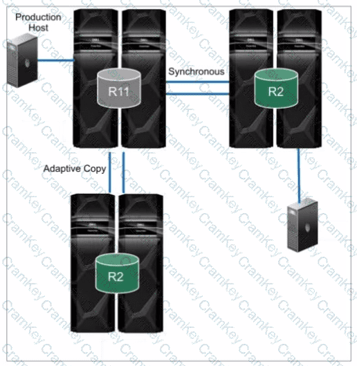
The topology shown in the exhibit depictsCascaded SRDF. This SRDF configuration involves three storage arrays (or sites) connected in a chained or cascaded manner.
Here's how it works:
Primary Site (R1):The production host is connected to the primary storage array (R1).
Intermediate Site (R2):The primary array (R1) synchronously replicates data to an intermediate array (R2).
Remote Site (R2):The intermediate array (R2) then asynchronously replicates data to a remote array (also labeled R2 in the diagram).
This cascading setup provides a multi-hop disaster recovery solution, where data is first replicated synchronously to a nearby site for high availability and then asynchronously replicated to a further remote site for disaster recovery.
Why other options are incorrect:
B. SRDF/Star:SRDF/Star involves a central array replicating to multiple remote arrays in a star-like pattern.
C. SRDF/Metro:SRDF/Metro is designed for synchronous replication over short distances, typically within a metropolitan area.
D. Concurrent SRDF:Concurrent SRDF allows multiple SRDF relationships to exist simultaneously for the same device.
References and documents of Dell's public documentation for PowerMax Operate v.2:
Dell Solutions Enabler 10.0.0 SRDF Family CLI User Guide:This guide provides detailed information about different SRDF configurations, including Cascaded SRDF. You can find this document on the Dell Support website by searching for "Solutions Enabler SRDF Family CLI User Guide."
Dell PowerMax Family: Essentials and Best Practices Guide:This guide offers a comprehensive overview of SRDF and its functionalities, including various topologies and use cases.